liftmaster photo eye wiring diagram
Logic 50 Wiring Diagram. Easily Find What You Need by Searching Our Site With Your Model Number.

Liftmaster Low Power Plug In Loop Detector Loopdetlm
Ad We Offer a Comprehensive List of Genuine Liftmaster Parts.

. Twist together the two white-with-black-stripe wires from both sensors. Single Phase Logic 50 Diagram. Three Phase Logic 50 Diagram.
Strip 716-inch of insulation from each solid-white and white-with-black-stripe wire on both sensors. To download the diagrams click the links below.

Liftmaster Insl24ul Commercial Slide Gate Opener Instruction Manual Manuals

Liftmaster Auxcard Auxiliary Contacts Option Board For Logic 4 And 5 Commercial Door Operators
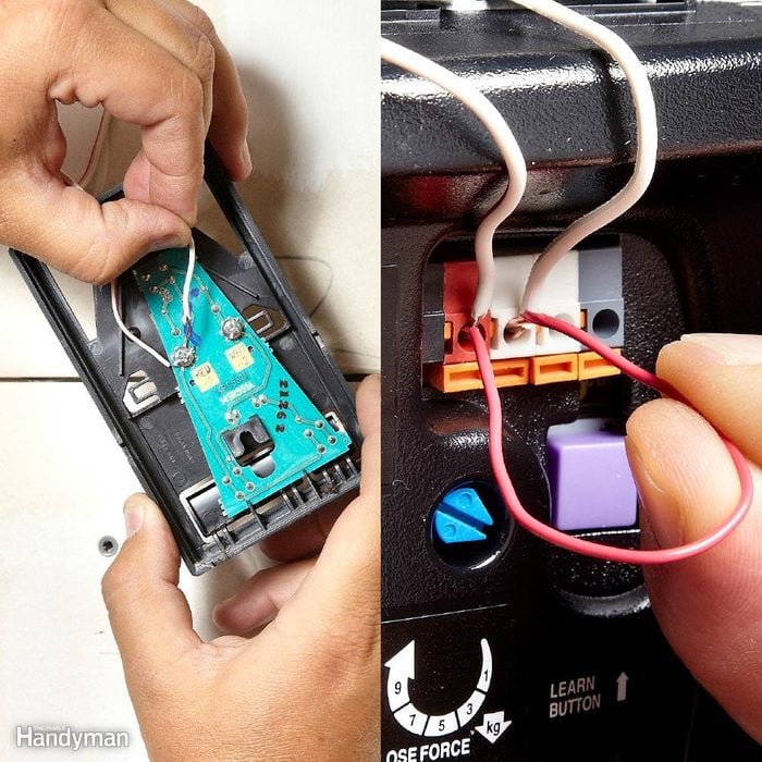
Garage Door Opener Repair And Troubleshoting
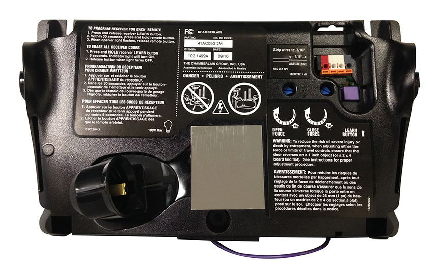
Home Improvement Home Garden Liftmaster 41ac075 2a Garage Door Opener Logic Control Board 315 Mhz Garage Doors Curridabat Go Cr
Knocklock Wiring Diagrams
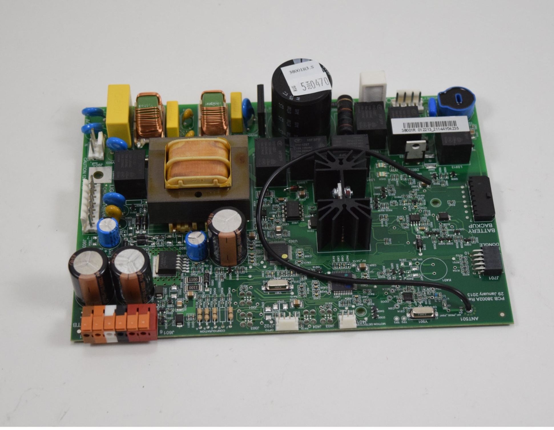
Why Does My Garage Door Opener Work Intermittently
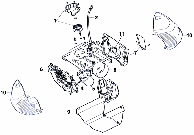
Select Products Parts Garage Door Opener Parts Residential Liftmaster Liftmaster Belt Drive Model 3850 Gatehousesupplies Com

Liftmaster Cps Rpen4 Monitored Retro Reflective Photo Eye
Garage Door Wiring Diy Home Improvement Forum

Garage Door Obstruction Sensor Repair 9 Steps With Pictures Instructables

Garage Door Operator Prewire And Framing Guide
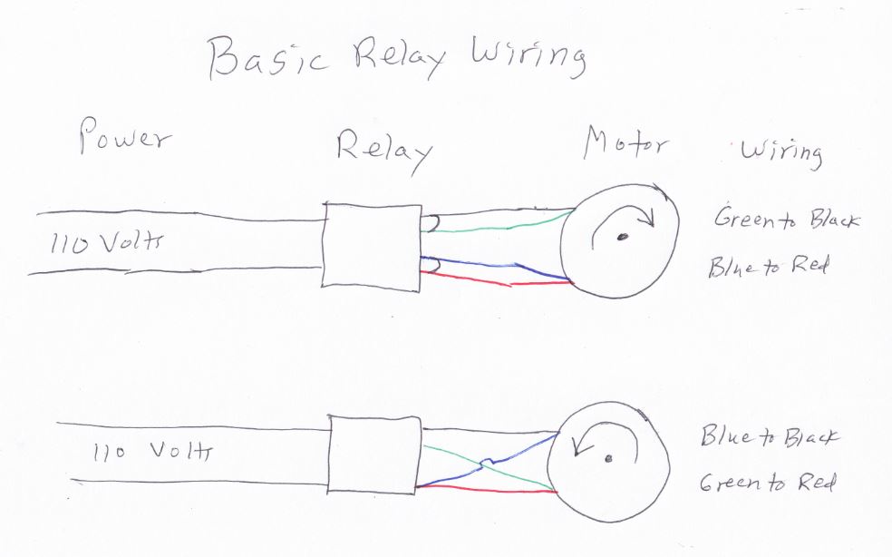
Functions Of A Liftmaster Logic 5 Control Board Ddm Garage Doors Blog Dan S Garage Door Blog

Amazon Com Liftmaster Lmrrul Retro Reflective Photo Eye Tools Home Improvement

Wiring Diagram For Garage Door Opener Garage Door Sensor Garage Doors Liftmaster Garage Door Opener

Liftmaster Garage Door Opener Opens But Won T Close How To Fix It
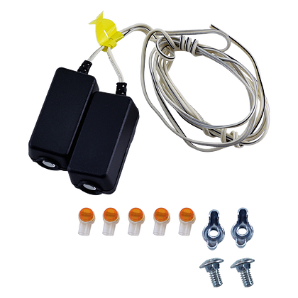
041a5034 Safety Sensor Kit Parts Liftmaster
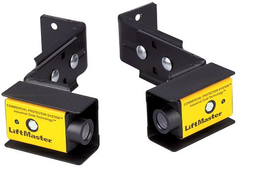
Cps U Commercial Photo Eyes Liftmaster Canada